
Thursday, 29 August 2013
LCD DISPLAY USING 3 WIRE
Friday, 28 June 2013
Making PCB using Toner transfer method
Making a PCB is very simple; it does not consume a lot of time and
the results look professional. After reading this How-To and watching
the step by step video, you will be able to make your own PCB in your
workshop using just a few inexpensive materials.
Many people use protoboard and point-to-point wire everything, but needing multiple copies of the same circuit is the reason that forces many away from using protoboard. After making your first circuit board, you might not point-to-point wire anything again!
For your first circuit board, one goal is to keep the circuit single sided so you can etch using single sided copper clad. This will allow you to gain some experience before moving on to double-sided
Here is a list of materials you will need to produce a single-sided board. With the exception of the copper clad and PCB drills, everything on this list is easily obtained at your local store.
1.Copper clad
2.FeCl3 solution or powdered form for etching
3.Laser printer
4.Drill machine
5.PCB designing software.
I bought copper clad for rs 60 from Lajpat Rai market,Size 1sq ft.just go to any pcb shop and ask for copper clad.

Laser printers are easy available from your near by internet cafe or photostat shop.Make sure to ask them that the printer they are using is Laser or inkjet.Any printer other than Laser cannot do the task.So a laser printer is must.

Drill machine is also available at lajpat rai from shop no 200.it cost me 90 rs and its 1mm bead for 20 rs extra.

For PCB designing any suitable PCB software can be used.I did mine in ORCAD.
Now what about FeCl3?I got it from a friend of my pursuing graduate degree.I ask him and he did brought it from his lab.So just go and find your undergraduate friend.

Now, here is how you do it:

Print the bottom side layer on a piece of paper from a high quality magazine or photopaper. Use one actual page from the magazine, the thicker and shinier the magazine paper the better, but do not use the cover. You must use a laser printer, not an inkjet. If your printer uses ink cartridges and not toner cartridges, it will not work. If you do not have a laser printer, you can work around this by printing to white paper and using a photocopier set to the darkest setting to copy the layout to the magazine paper.
I used a photo paper cost only rs 10 to print the circuit.Almost every stationary have it.
Magazine pages are used because they work well, and they are cheap! The reason they work is because the paper is very glossy and the toner does not adhere well to the glossy pages. The printing used on the magazine page is ink and it does not come off, but toner does. Toner is actually a plastic polymer, and different toners may yield varied results

Very carefully, remove the copper clad from the packaging. Do not touch the copper surface for the same reason as above. You can cut the copper clad to size using a tin snip if needed. Use the Scotch Brite scrubbing pad to gently buff the surface (Scotch Brite is a popular brand of of plastic scrubbing pad meant to emulate steel wool). Do not use steel wool because it will embed steel into the copper. Clean off the residual dust with a slightly damp paper towel. Use a kitchen scrubber or a fine sandpaper and sand the copper. Do not overdo it.Clean the surface with a cloth. Do not touch the surface once the cleaning is done.

Now that the board and the print are ready, switch on your clothes iron to the maximum heat and leave it for a minute or two.Align the printed paper on the copper board with the printed side over the board.Applying a bit of pressure, carefully move the iron on the paper for 2 - 3 minutes.If you have long lines in your PCB, they tend to not get transfered completely.


Bolster the lines on your copper board.To bolster the line, you can trace that line with a sharpie or a paint pen(works better). if you have a black electrical tape, you can use that as well. Cut it really thin(as thick as the line) and cover the line with the tape.
Etching Process
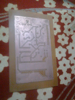
Drop the board into water and carefully peel off the paper and you should see the print on the board. If the paper does not peel off easily, remove it by rubbing it slightly.Prepare the etching solution with FeCl3 and water in a ratio of 150ml with 50g of FeCl3.Gloves and eye protection are recommended!Drop the board into the solution and wait for a couple of seconds.When the fine tracks are clearly visible and the unwanted copper removed, take the board out and clean it in water.


Place the board face up in the STRIP tray, and coat it with resist stripper. This may be in a bottle or in a 'shoepolish' dispenser. Rub in the chemical first with the soft sponge, then with with a plastic scrub pad. The green resist should come off, revealing copper underneath. Make sure -all- of the resist is removed, as it smells very bad when it gets hot (when soldering.) If there is no stripper, you can just scrub it off with a green scrub pad. If the stripper came from a bottle, pour it back in. Rinse off the board and tray.


 Get start with the drill machine and place your components.
Now your own professional PCB is ready to use.


Many people use protoboard and point-to-point wire everything, but needing multiple copies of the same circuit is the reason that forces many away from using protoboard. After making your first circuit board, you might not point-to-point wire anything again!
For your first circuit board, one goal is to keep the circuit single sided so you can etch using single sided copper clad. This will allow you to gain some experience before moving on to double-sided
Here is a list of materials you will need to produce a single-sided board. With the exception of the copper clad and PCB drills, everything on this list is easily obtained at your local store.
1.Copper clad
2.FeCl3 solution or powdered form for etching
3.Laser printer
4.Drill machine
5.PCB designing software.
I bought copper clad for rs 60 from Lajpat Rai market,Size 1sq ft.just go to any pcb shop and ask for copper clad.

Laser printers are easy available from your near by internet cafe or photostat shop.Make sure to ask them that the printer they are using is Laser or inkjet.Any printer other than Laser cannot do the task.So a laser printer is must.
Drill machine is also available at lajpat rai from shop no 200.it cost me 90 rs and its 1mm bead for 20 rs extra.
For PCB designing any suitable PCB software can be used.I did mine in ORCAD.
Now what about FeCl3?I got it from a friend of my pursuing graduate degree.I ask him and he did brought it from his lab.So just go and find your undergraduate friend.
Now, here is how you do it:

Print the bottom side layer on a piece of paper from a high quality magazine or photopaper. Use one actual page from the magazine, the thicker and shinier the magazine paper the better, but do not use the cover. You must use a laser printer, not an inkjet. If your printer uses ink cartridges and not toner cartridges, it will not work. If you do not have a laser printer, you can work around this by printing to white paper and using a photocopier set to the darkest setting to copy the layout to the magazine paper.
I used a photo paper cost only rs 10 to print the circuit.Almost every stationary have it.
Magazine pages are used because they work well, and they are cheap! The reason they work is because the paper is very glossy and the toner does not adhere well to the glossy pages. The printing used on the magazine page is ink and it does not come off, but toner does. Toner is actually a plastic polymer, and different toners may yield varied results

Very carefully, remove the copper clad from the packaging. Do not touch the copper surface for the same reason as above. You can cut the copper clad to size using a tin snip if needed. Use the Scotch Brite scrubbing pad to gently buff the surface (Scotch Brite is a popular brand of of plastic scrubbing pad meant to emulate steel wool). Do not use steel wool because it will embed steel into the copper. Clean off the residual dust with a slightly damp paper towel. Use a kitchen scrubber or a fine sandpaper and sand the copper. Do not overdo it.Clean the surface with a cloth. Do not touch the surface once the cleaning is done.

Now that the board and the print are ready, switch on your clothes iron to the maximum heat and leave it for a minute or two.Align the printed paper on the copper board with the printed side over the board.Applying a bit of pressure, carefully move the iron on the paper for 2 - 3 minutes.If you have long lines in your PCB, they tend to not get transfered completely.


Bolster the lines on your copper board.To bolster the line, you can trace that line with a sharpie or a paint pen(works better). if you have a black electrical tape, you can use that as well. Cut it really thin(as thick as the line) and cover the line with the tape.
Etching Process
Drop the board into water and carefully peel off the paper and you should see the print on the board. If the paper does not peel off easily, remove it by rubbing it slightly.Prepare the etching solution with FeCl3 and water in a ratio of 150ml with 50g of FeCl3.Gloves and eye protection are recommended!Drop the board into the solution and wait for a couple of seconds.When the fine tracks are clearly visible and the unwanted copper removed, take the board out and clean it in water.


Place the board face up in the STRIP tray, and coat it with resist stripper. This may be in a bottle or in a 'shoepolish' dispenser. Rub in the chemical first with the soft sponge, then with with a plastic scrub pad. The green resist should come off, revealing copper underneath. Make sure -all- of the resist is removed, as it smells very bad when it gets hot (when soldering.) If there is no stripper, you can just scrub it off with a green scrub pad. If the stripper came from a bottle, pour it back in. Rinse off the board and tray.


 Get start with the drill machine and place your components.
Now your own professional PCB is ready to use.


Tuesday, 26 March 2013
8051 BASED STOPWATCH
The project uses seven segment displays and 89S51 controller to control the stopwatch.The stopwatch is enabled to count from 0 to 99.After 99 the watch toggles to 00.A nice start for beginners.Go and have some fun with programming and hardware.C program and design file are attached below.
DOWNLOAD:C PROGRAM AND DESIGN FILE

DOWNLOAD:C PROGRAM AND DESIGN FILE

Bidirectional Visitor Counter
The circuit consist of very basic components like seven segments,8051 microcontroller and buttons can be replaced by IR sensor circuits.Button 1 is used to increment the counter while button 2 decrements the counter.The counter shows an increment up to 9.This project will be a very good start for begineers in programming.Just assemble the circuit and amaze your friends.Coding and design file of the project is attached below.
DOWNLOAD:C PROGRAM AND DESIGN FILE

DOWNLOAD:C PROGRAM AND DESIGN FILE

8051 Based Wind Turbine
A 8051 based wind
turbine model consist of a moving rotor assembly consisting of a DC motor including the blades for
converting wind energy to low speed rotational energy. The generator component
includes the electrical generator, the control electronics, and most likely a gearbox
(e.g. planetary gearbox, adjustable-speed drive or continuously variable
transmission) component for converting the low speed incoming rotation to high
speed rotation suitable for generating electricity.
The whole generator system is mounted on a stepper motor configuration which
enables the system to move 180 ͦ towards
left and 180 ͦ towards right direction. This
enables the system to move 360 ͦ and
choose the direction of the wind anytime. This eliminates the dependency of
wind turbine on the direction of wind.
The system is connected with a controlling keypad to move the stepper motor in desired
direction. At the base of the turbine tower is a energy storing system made of resistors and capacitors to store
the AC voltage produced during the rotation of turbine blades. The capacitor stores the fluctuating
voltage and converts it into constant voltage supply to drive LED or other kind
of load.
An LCD is
provided along with keypad to display the condition of wind speed depending on
the speed of the moving blades. The LCD also displays the degree at which the
turbine system mounted on stepper motor is moving.
The system is connected with an Atmel 89S52 microcontroller which
controls and manages the working of whole assembly including stepper motor,
keypad and LCD display.
Key features of this project are:
Ø
A DC motor is used to generate the power from
moving wind.
Ø
Capability of turbine to rotate in 360 ͦ direction to choose the optimum direction
of flowing wind.
Ø
Controlling of system using a keypad present at
the base of the tower.
Ø
Uses a LCD to display the angle rotated by the
turbine assembly through stepper motor.
Ø
The power is stored in a capacitor circuit to
convert the fluctuating voltage into dc voltage.
Ø
8051 based turbine system to control the turbine
mechanism and stepper motor controlling mechanism.
Ø
The microcontroller and LCD works on a +5V
supply.

Thursday, 17 January 2013
Low cost Audio amplifier using LM386
All that is needed to build an audio amp are a few external components most of which are decoupling capacitors. It is well suited to low power applications
and runs just fine on a 9 volt battery or any voltage supply from 4-12
volts. It has a low quiescent current drain of only 4mA so it won’t kill
a battery right away if you leave it on and idle. The gain is
internally set to 20 but the addition of an external resistor
and capacitor between pins 1 and 8 will increase the gain to any value
from 20 to 200. An increase in bass frequency can be facilitated by
adding a 10K resistor and .033 uf capacitor in series between pins 1 and
5.


Subscribe to:
Posts (Atom)