Sunday 11 December 2011
A DIGITAL CLOCK WITH ALARM USING AT89S52 MICROCONTROLLER
AT89S51/52 based Digital Clock without any Clock IC. It has 4 seven
segment display to display the Time.

DOWNLOAD:Hex file
Saturday 3 December 2011

Atmel 89S52 microcontroller

Download led blinking program:
https://rapidshare.com/files/73421935/led_blink.zip
Thursday 17 November 2011

Tuesday 4 October 2011
Remote Control Circuit Through RF Without Microcontroller

In remote section consist of an encoder (HT 12E) and a ASK transmitter. The encoder generates 8 bit address and 4bit data. We can set the address by using the DIP switch connected in A0 to A7 (pin 1 to 8 ) encoder. If we set an address in the remote section, the same address will be required in the receiver section. So always set same address in transmitter and receiver. Whenever we press any key in the remote the encoder generates corresponding 4bit data and send this data with 8bit address by using ASK transmitter. The transmitting frequency is 433MHz. The transmitter output is up to 8mW at 433.92MHz with a range of approximately 400 foot (open area) outdoors. Indoors, the range is approximately 200 foot.
TRANSMITTER CIRCUIT

At the receiver section ASK receiver is present. The receiver also operates at 433.92MHz, and has a sensitivity of 3uV. The ASK receiver operates from 4.5 to 5.5 volts-DC, and has both linear and digital outputs. It receives the datas from the transmitter. Then the decoder (HT 12D) decodes the data and it will enable the corresponding output pin (pin 10,11,12,13).
RECEIVER CIRCUIT

For relay connection input the pins going to led to cd4017 and make ground common for both circuit.add 6volt relay to the cd4017 circuit at point A and B.

Monday 18 July 2011
Thursday 7 July 2011
Wednesday 29 June 2011
THE 434 MHZ ASK TRANSMITTER AND RECEIVER MODULE
The RF module, as the name suggests, operates at Radio Frequency. The corresponding frequency range varies between 30 kHz & 300 GHz. In this RF system, the digital data is represented as variations in the amplitude of carrier wave. This kind of modulation is known as Amplitude Shift Keying (ASK).
Transmission through RF is better than IR (infrared) because of many reasons. Firstly, signals through RF can travel through larger distances making it suitable for long range applications. Also, while IR mostly operates in line-of-sight mode, RF signals can travel even when there is an obstruction between transmitter & receiver. Next, RF transmission is more strong and reliable than IR transmission. RF communication uses a specific frequency unlike IR signals which are affected by other IR emitting sources.
This RF module comprises of an RF Transmitter and an RF Receiver. The transmitter/receiver (Tx/Rx) pair operates at a frequency of 434 MHz. An RF transmitter receives serial data and transmits it wirelessly through RF through its antenna connected at pin4. The transmission occurs at the rate of 1Kbps - 10Kbps.The transmitted data is received by an RF receiver operating at the same frequency as that of the transmitter.
The RF module is often used alongwith a pair of encoder/decoder. The encoder is used for encoding parallel data for transmission feed while reception is decoded by a decoder. HT12E-HT12D, HT640-HT648, etc. are some commonly used encoder/decoder pair ICs.
Receiver Transmitter


Tuesday 28 June 2011
A DIY BOOK FOR BEGINEERS RELATED TO 555TIMER CIRCUITS
HERE IS A BOOK THAT CONSIST OF 50 CIRCUITS INVOLVING 555 TIMER IC AND SOME BASIC COMPONENTS.A VERY NICE START FOR THE BEGINEERS UNDERSTANDING THE BASIC WORKING OF THE TIMER IC.ENJOY!!!
50-555Circuits
Sunday 26 June 2011
A 555 TIMER LED FLASHER CIRCUIT
CIRCUIT DIAGRAM OF 555TIMER IN ASTABLE MODE

An astable multivibrator, often called a free running multivibrator, is a rectangular wave generating circuit. The circuit doesnt need any triggering. The timing of the circuit is determined by the resistors and the capacitors used in it. The details of the astable multivibrator are:
Pin1 is grounded; Pins 4 and 8 are shorted, Pin 3 gives the timing output; Pins2 and 6 are short circuited and connected with a capacitor C1; at Pin 5 a bypass capacitor is used having value of 0.01uF; a supply of 3v is given to the circuit, the suppy can be more upto 9v. Pin 7 is connected through Pin 4 through a resistor R1and also with pin 6 through resistor R2.
The output pin 3 of the circuit is connected with a led having positive side in the pin 3 and negative side with the ground.
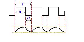
The overall oscillation period of the circuit an be determined by
T = 0.693.(R1 + R2).C1 + 0.693.R2.C1 = T,high + T,low
where T,high = 0.693.(R1 + R2).C1
T,low = 0.693. R2. C1
Also,
the frequency of oscillations= 1/T =1.44 / ( R1 + 2R2).C
PIN CONFIGURATION OF A 555 TIMER

OUTPUT WAVEFORMS
Here is a video showing the working of a 555 timer in astable mode:
Saturday 25 June 2011
A SIMPLE DECADE COUNTER USING LM555 TIMER AND CD4017

The number of seven segments required for this decade counter is obviosly ten.The connection of a seven segment will we shown later in this forum.
The capacitor having value 0.01uF is just an ordinary ceramic capacitor which can be easily digged out of spare circuits having printed 103 on them.The capacitor c1 is an electrolytic capacitor having value 100uF.The resistance value can be changed to get the desired pulse timings.For any queries ,please post here.
Subscribe to:
Posts (Atom)